Surface Finish Callout On Drawing
The surface of CNC machined parts varies from shiny to smooth to rough, the roughness will affect the performance of the component. What surface finish or roughness are required and how to indicate roughness in drawing? In this article, we'll explain the surface roughness symbols, indication, grade numbers, terminology and calculation.
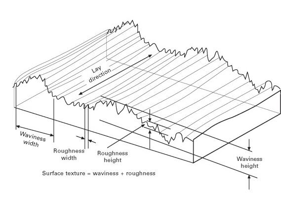
What is Surface Roughness?
Surface roughness or roughness, is a measure of surface irregularities. It is defined as the shorter frequency of real surfaces relative to the troughs. Roughness is quantified by the deviations in the direction of the normal vector of a real surface from its ideal form, if the deviations are large, the surface is rough, if they are small, the surface is smooth. Roughness generally caused by a manufacturing process or material condition. The mean arithmetical value "Ra" in μm is assumed for roughness measurements.
ISO Surface Roughness Symbols
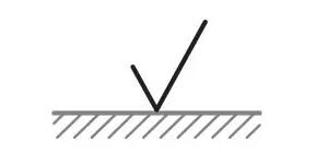
Surface roughness symbols are used to communicate the required surface texture of machined and structural parts are used in industrial diagrams. The pictorial representation using these symbols is defined in ISO 1302:2002. Check out the uses and images of different roughness symbols below.
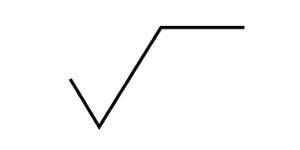
1. Basic shaped roughness symbol. It is consists of two lines of unequal length inclined at an angle of approximately 60 degrees to the line representing the considered surface, the symbol must be indicated by thin lines. Surface texture obtained by any manufacturing process, such as CNC turning, grinding, bending, etc.
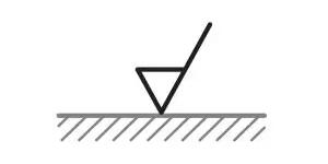
2. This symbol has a bar added to the basic symbol, and forms a triangle. it indicates a surface that requires a material removal process and allowance indicated. Surface texture obtained by the removal of material by machining operations like turning, drilling, milling, etc.
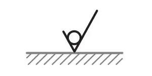
3. This symbol has a circle added in the groove of the basic shaped symbol. It indicates a surface where removal processes are not permitted.
4. This symbol has a bar added to the top of the right side of the basic symbol. It indicates special surface characteristics.
Surface Roughness Indication
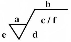
The surface roughness is generally indicated with the symbol and displays information including surface roughness value, cutoff value, machining method, sampling length, surface waviness and crease direction symbol as below.
a: roughness value in micrometers preceded by parameter symbol
b: production method
c: waviness height preceded by parameters symbol or sampling length in millimeters
d: surface pattern
e: machine allowance
f: roughness value other than Ra in micrometers
Surface Roughness Terminology
1. Roughness: Roughness consists of surface irregularities which result from the various machining process. These irregularities combine to form surface texture.
2. Roughness Height: It is the height of the irregularities with respect to a reference line. It is measured in millimeters or microns or microinches. It is also known as the height of unevenness.
3. Roughness Width: The roughness width is the distance parallel to the nominal surface between successive peaks or ridges which constitute the predominant pattern of the roughness. It is measured in millimeters.
4. Roughness Width Cut Off: Roughness width cut off is the greatest spacing of respective surface irregularities to be included in the measurement of the average roughness height. It should always be greater than the roughness width in order to obtain the total roughness height rating.
5. Lay: Lay represents the direction of the predominant surface pattern produced and it reflects the machining operation used to produce it.
6. Waviness: This refers to the irregularities which are outside the roughness width cut-off values. Waviness is the widely spaced component of the surface texture. This may be the result of workpiece or tool deflection during machining, vibrations, or tool run out.
7. Waviness Width: Waviness height is the peak to valley distance of the surface profile, measured in millimeters.
8. Arithmetic Average (AA): A close approximation of the arithmetic average roughness-height can be calculated from the profile chart of the surface. Averaging from a mean centerline may also be automatically performed by electronic instruments using appropriate circuitry through a meter or chart recorder.
Surface Roughness Grade Numbers
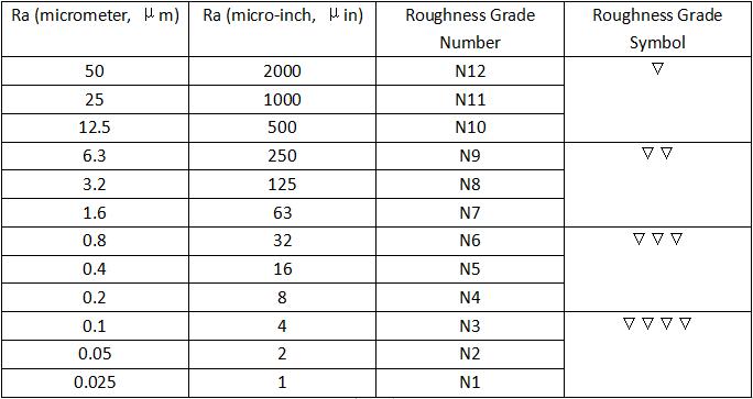
Here is a chart shows how roughness grade numbers convert to Ra values and roughness symbols.
Surface Roughness Calculation
Average Roughness in micro-meters or micro-inches. Ra is the arithmetic mean deviation of the profile.
Ra = CLA = (M1 + M2 + M3 + M4)/4
M1, M2, M3, M4 are measure values
CLA is center line average
Surface Finish Callout On Drawing
Source: https://www.cnclathing.com/guide/surface-roughness-symbols-grade-numbers-indication-terminology-and-calculation-cnclathing
Posted by: farrellfroma1981.blogspot.com

0 Response to "Surface Finish Callout On Drawing"
Post a Comment